Registrations
We now manually approve all new user accounts due to a large influx of spam bots. Accounts are normally approved within 48 hours.
If you need any help with using this Wiki, please ask here: TalkFord.com Wiki Submission Forum
Difference between revisions of "Stereo Connectors - Pre-Facelift"
| Line 49: | Line 49: | ||
Pin 3 Not Used | Pin 3 Not Used | ||
| − | Pin 4 (Black/Red) Telematics | + | Pin 4 (Black/Red) Telematics - When fitting Handsfree phone kits, this is where the stereo mute wire goes |
| − | Pin 5 (White) Telematics | + | Pin 5 (White) Telematics |
Pin 6 (White/Green) VSS | Pin 6 (White/Green) VSS | ||
Revision as of 06:00, 17 September 2009
Note: This wiring information does not cover pre-facelift Navigation Systems, although some of the information may still be relevant/correct
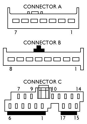
The following figures illustrate the basic connector layouts and give pin numbers which correspond to the lists below.
Contents
Connector A (C483)
Power (with RSE = C489)
Pin 1 (Orange/Black) Battery + (From Fuse F72) (20A)
Pin 2 (Black/Yellow) Keycode Ground
Pin 3 (Blue/Black) Ign. Sense (Accessory) (From Fuse F69) (7.5A)
Pin 4 (Orange/Black) Illumination
Pin 5 (Black/Orange) Alarm Sense (From GEM)
Pin 6 (Black/Green) Ground
Pin 7 (Orange/Green) Not Used on C483 / To multimedia control module on cars with Rear Seat Videos (C489) / To telematics module on cars with phone prep (C1003)
Connector B (C484)
Speakers
Pin 1 (White/Black) Left Front –
Pin 2 (Grey/Black) Left Front +
Pin 3 (White/Violet) Left Rear –
Pin 4 (Grey/White) Left Rear +
Pin 5 (White/Red) Right Front –
Pin 6 (Grey/Red) Right Front +
Pin 7 (White/Right) Rear –
Pin 8 (Grey/Right) Rear +
Connector C (C485)
Data
Pin 1 (Grey/Black) Telematics
Pin 2 (Blue/Yellow) Telematics
Pin 3 Not Used
Pin 4 (Black/Red) Telematics - When fitting Handsfree phone kits, this is where the stereo mute wire goes
Pin 5 (White) Telematics
Pin 6 (White/Green) VSS
Pin 7 Not Used
Pin 8 (White/Red) Telematics
Pin 9 (White/Red) Telematics
Pin 10 (Green/White) Reverse Sense (For Navigation)
Pin 11 (White/Black) Steering Column Remote Stalk
Pin 12 (Brown/Yellow) Steering Column Remote Stalk
Pin 13 Not Used
Pin 14 Not Used
Pin 15 Not Used
Pin 16 (White/Green) Data Link Connector
Pin 17 (Black/Green) Restraints Control Module / Telematics
Submitted by DJAZS

 Your Privacy Choices