Registrations
We now manually approve all new user accounts due to a large influx of spam bots. Accounts are normally approved within 48 hours.
If you need any help with using this Wiki, please ask here: TalkFord.com Wiki Submission Forum
Difference between revisions of "Quadlock Stereo Connector - Facelift"
(→Connector C) |
m (→Connector B) |
||
| Line 42: | Line 42: | ||
Pin 16 Ign. Sense (Accessory) | Pin 16 Ign. Sense (Accessory) | ||
| − | ==Connector B== | + | ==Connector B (C520)== |
Pin 1 Mono + | Pin 1 Mono + | ||
| Line 66: | Line 66: | ||
Pin 11 Rev Sense | Pin 11 Rev Sense | ||
| − | Pin 12 AVC | + | Pin 12 AVC |
==Connector C== | ==Connector C== | ||
Revision as of 11:26, 3 January 2009
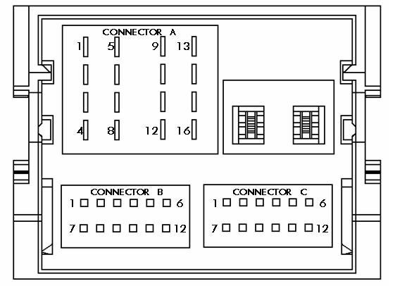
Note: This wiki article details the functions of all pins in the Quadlock connector. Depending upon the stereo specification, several of the pins will be unused.
The following figure illustrates the connector layout and gives pin numbers which correspond to the lists below.
Connector A
Speakers
Pin 1 Right Rear +
Pin 2 Right Front +
Pin 3 Left Front +
Pin 4 Left Rear +
Pin 5 Right Rear –
Pin 6 Right Front –
Pin 7 Left Front –
Pin 8 Left Rear –
Power
Pin 9 CAN +
Pin 10 CAN –
Pin 11 Keycode Ground
Pin 12 Ground
Pin 13 Alarm Sense
Pin 14 Illumination
Pin 15 Battery +
Pin 16 Ign. Sense (Accessory)
Connector B (C520)
Pin 1 Mono +
Pin 2 Sw A+
Pin 3 Aux L+
Pin 4 Aux R +
Pin 5 PTA
Pin 6 SWC
Pin 7 Mono -
Pin 8 SWC Gnd
Pin 9 Aux L –
Pin 10 Aux R –
Pin 11 Rev Sense
Pin 12 AVC
Connector C
Pin 1 RSE L+ (Rear Seat Entertainment)
Pin 2 RSE R+ (Rear Seat Entertainment)
Pin 3 Mono 2 +
Pin 4 Sub W +
Pin 5 Aux 2 L
Pin 6 Audio Gnd
Pin 7 RSE L – (Rear Seat Entertainment)
Pin 8 RSE R – (Rear Seat Entertainment)
Pin 9 Mono 2 –
Pin 10 Sub W –
Pin 11 Aux 2 R
Pin 12 Mic.
Submitted by DJAZS

 Your Privacy Choices