Registrations
We now manually approve all new user accounts due to a large influx of spam bots. Accounts are normally approved within 48 hours.
If you need any help with using this Wiki, please ask here: TalkFord.com Wiki Submission Forum
Interior Door Handle Illumination
For more information, visit the Ford Mondeo forum on TalkFord.com, the definitive resource site covering all Fords from the present day to the 1970's.
|
Overview Guide | |
| Ford Model: | Mondeo Mk3 |
|---|---|
| Petrol/Diesel: | both |
| Estimated Cost: | not much |
| Difficulty? | needs wiring skill |
| How long does this take? | 1hr per door |
For the Mk3 Mondeo...
Imagine the situation - you're courting an attractive young lady, the evening's gone well, and you're dropping her off at her home in a dark street. You share a light kiss, she opens the door and she's gone for the night. Later, things develop well, and you marry and raise a family. One of your children goes on to be the chief scientist on the SpaceGuard programme that successfully saves the earth from destruction by an oncoming asteroid. Good news indeed.
But let's rewind to that first evening. Assume that your lady friend cannot find the door handle in the dark, as you've left the engine running and the courtesy light hasn't come on. She giggles nervously as she tries to find the handle, feeling awkward and uncomfortable. In an attempt to put her at her ease, you laugh too - but she interprets this as mockery! Things go downhill from here, and you split up; she instead falls for a man with a top-spec Mk2, which already has illuminated handles. Later, everyone dies in a hideous fireball when the earth is struck by an oncoming asteroid.
I think it's clear why this is such a critical modification.
Here's how to get illuminated interior door handles on your Mk3. You can fit this in any door that has electric windows, as it uses the ignition-live feed that illuminates the switches. If you have a facelift LX with manual rear windows, you're on your own (you could, of course, upgrade to electric rear windows). Note that the rear electric window disable switch on the driver's door also disables the illumination on the rear switches, so your rear handle lights will go out too. This is a feature, not a bug, as you can choose when to turn them on for maximum wow factor from your rear passengers.
If you do it properly and carefully, it'll take at least an hour per door: 20 minutes to build the LED loom, 40 minutes to install it.
Contents
Parts needed per door
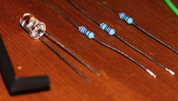
- 5mm LED in chosen colour. Choose a fairly bright version.
- Suitable resistor. I used 3x270ohm in series for a red LED to give 810 ohms total, a bit more than needed but good for lifetime and robustness. I used multiple resistors to reduce the power dissipation of each. See Calculating LED Resistor Values.
Alternatively, you could use a 12V LED which has the correct resistor built in. I prefer to use the raw components as they're cheaper, more flexible with regards to component choice, and available in a wider range. You could even use small bulbs, 286-size or smaller - but watch out for heat and power consumption. Adding four 3W bulbs will add 1A to the ignition-live circuit draw.
- Wire, either twin or two separate lengths. You'll need about 40cm per door, and you'll need to be able to distinguish the two wires.
- Various bits of heatshrink if you want to do it properly, insulting tape if you can't be bothered.
- Tape for fixing your new wiring to the door.
- Some form of milky white plastic sheet. I used a 4 pint Asda milk bottle, but ensure that the bottle is empty before you cut it, and wash the plastic really well to avoid nasty off milk smells.
- Decent glue. I used SuperGlue (cyanoacrylate).
Tools needed
- Soldering iron and solder. Seriously, don't mess around with twisting and taping, or with chocolate block connectors.
- Tools for cutting / stripping wire. I prefer to strip insulation by melting the "cut point" with the soldering iron and pulling the insulation off, as that avoids damage to the already-thin conductors.
- Thin knife or other sharp point for removing handle screw cover and mirror sail screw cover.
- Cross-head (Philips) screwdriver for the door card screws.
- T25 Torx driver for the door handle recess screw. You might get lucky with the right-sized flat blade screwdriver, but don't come crying if you strip it.
- Flat-blade screwdriver or other hard flat tool for removing the door pull cover.
- 5mm drill bit.
- Some method of cutting a roughly rectangular hole in plastic. I bodged it with multiple 3mm holes with a drill plus some filing. Neatness is not critical, as the hole won't be seen.
Build LED loom
Before you start taking the car apart, construct the LED loom.
The LED will probably have a flat bit at the base of its plastic case (visible at the right hand side in the above photo): this shows which leg is the cathode (negative).
- 40cm of wire off each leg of the LED
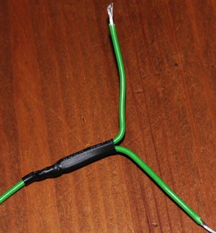
- Y-pieces at the ends of the wires to allow you to connect your new wiring neatly into the cut door wiring:
- Put the series resistor(s) in line with the positive wire (omit if using 12V LEDs):
As above, use plenty of heatshrink to cover all joints. Electrical insulation is very important.
Remove door card
See Removal Of Door Cards - Mk3.
Drill hole
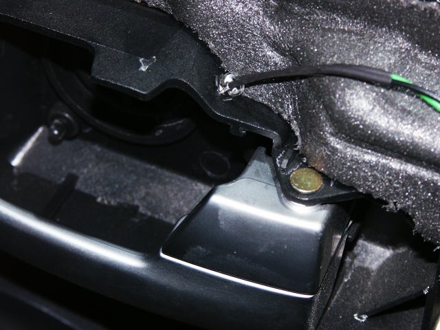
In the plastic door handle surround attached to the door (not the bit on the door card) drill a 5mm hole on the "slope", ideally closer to the car centre than the door. In the photos below, I've drilled it a little too close to the door.
Putting it here:
- gives easy access to the drill point
- makes for good even light spread in the handle recess without the light source being visible
- keeps all the electrics on the door rather than the complications of adding wires to the door card
Fit LED
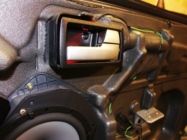
Push the LED into the hole, taking care not to bend the leads too much. Ideally, the hole will be tight enough for a push-fit, but if it isn't, use a suitable glue or putty to secure it.
Then secure the wiring to the door membrane using suitable tape. Try to ensure that the LED's leads are not under tension or free to vibrate, which may lead to fatigue failure. Note that the plastic security shield on the door card will press the wires against the membrane - see the impression in the membrane in the photo above.
Install wiring
Make sure the ignition is off at this point!
First, identify the switch illumination wires using, for example, the Haynes wiring diagrams. Look out for the German colour abbreviations: there's a key at the top of the diagrams. In my pre-facelift Graphite with front and rear electric windows, these are as follows - yours should be the same:
- Driver's door: Green/Yellow is positive (clearly not decided by a domestic electrician!), Black is ground. There are a lot of "black with a stripe" wires, but only one pure black wire (although it's more of a dark grey on mine).
- Passenger front door: Green/Blue (goes to pin 1 on the switch connector) is positive, Black (pin 6) is ground.
- Both rear doors: Green/Red (pin 1) positive, Black/Orange (pin 6) negative. Beware - there are, rather unhelpfully, two black and orange wires on the rear switch wiring. Get the right one by following it out of pin 6 as labelled on the face of the connector.
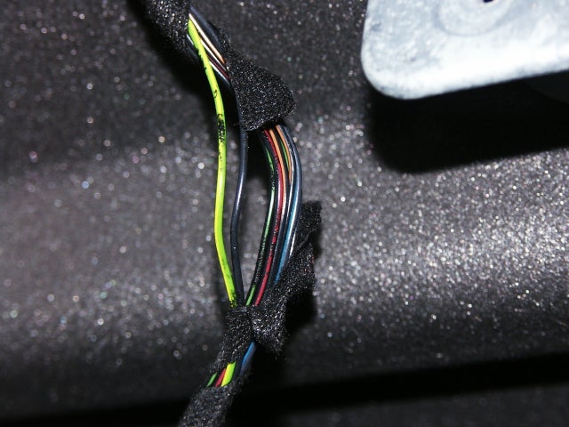
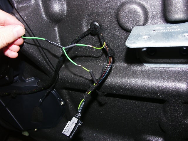
Cut and unwrap some of the fabric cable wrap about 6" away from the connector. Separate the wires you need from the bunch, cut and strip them. Tin the ends with solder, then, when cool, fit a bit of unshrunk heatshrink ready to cover the joint when you've made it. Make sure it's waiting far enough away from the end that it doesn't get shrunk when you make the solder joint.
Here, I've separated out the two wires I need from the driver's door loom:
Tin the ends of your LED loom, and solder in the wiring. Slide the heatshrink over the join, and shrink using heat from the iron. Be sure to not melt any insulation or burn a hole in the door membrane.
Here it is, joined up but not yet insulated - note the heatshrink pre-threaded onto the wires:
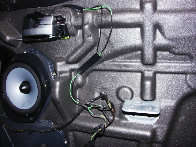
...and the completed wiring job:
Once you have the LED loom wired in, make sure it illuminates when you turn the ignition on (and for the rears, the override switch in the driver's door must be off (red light)).
I've subsequently hot-glued the wiring to the door in various places to secure it and reduce the risk of future rattling.
Cut window in handle cup
With the door card still off, and the LED fitted, install the handle trim "cup" into position. Check alignment with the Torx screw hole, making sure it's pushed right back and the little alignment peg is in place.
Turn the LED on (ignition; and for the rears, enable the rear windows from the driver's door switch) and note the area on the top of the cup that it illuminates. Switch off again and remove the cup.
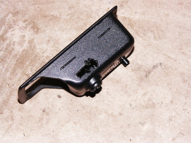
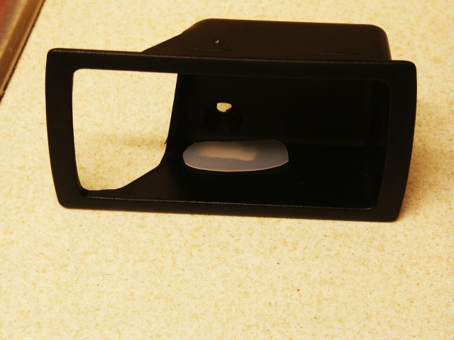
Using whatever means you have, cut a suitable hole in the cup to allow the light through. It doesn't need to be neat as it'll be covered up, but take care not to damage the other visible plastic surfaces in the cup.
Reinstall the cup to check that the hole is in the correct place: all of the LED's beam should go through it. Remove the cup, and enlarge the hole further if necessary.
Checking alignment:
Cut a flat piece of milky white plastic (milk bottles are good) to be stuck to the inside of the cup to cover the hole. This diffuses the beam giving soft, even illumination. Leave enough spare around the edge to glue it to the plastic surrounding the hole. Glue it on, observing the usual safety precautions for the adhesive you choose. Leave to dry.
Reassemble
Refit the door card and mirror sail cover (fronts). Don't forget to connect the window switch! Insert your modified cup and try it out.
If, after testing, you decide the light is too bright, you can dim it down by removing the cup and gluing another layer of plastic on top of the hole. There's no need to remove the door card to make this adjustment.
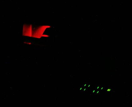
Here's a photo of the finished article, in comparison with the window switches. This over-emphasises the brightness of both - the handle illumination is invisible until it's dark enough to be useful.
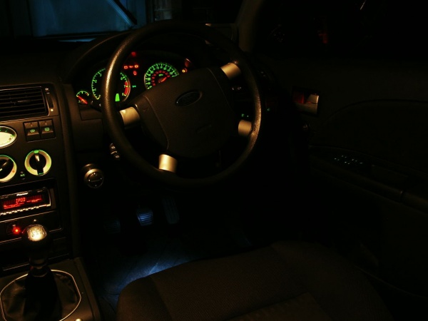
...and another showing all the interior lighting as a comparison, including the stock courtesy lamp. Everything is standard apart from:
- ICE
- LPG system LED just below it
- White LED footwell lamps
- ...and, of course, the new door handle illumination.
You can see that under even low lighting, the door handle illumination fades unobtrusively into the background:
Once you've done this, you could take the next step and add courtesy illumination to the handle. This requires either an existing puddle light feed in the door to tap into, or running a pair of extra wires into each door from the footwell lamps.



 Your Privacy Choices