Registrations
We now manually approve all new user accounts due to a large influx of spam bots. Accounts are normally approved within 48 hours.
If you need any help with using this Wiki, please ask here: TalkFord.com Wiki Submission Forum
Difference between revisions of "FSE Power Boost Valve HowTo"
(New page: How to Fit a FSE Power Boost Valve Kit Required [http://i3.photobucket.com/albums/y92/arabianjules/mymondySi/FSE%20fit/img_fsekit.jpg Parts] http://www.fuelsystem.co.uk/pbv.htm FITT...) |
|||
| Line 1: | Line 1: | ||
| − | How to Fit a FSE Power Boost Valve | + | == How to Fit a FSE Power Boost Valve == |
| − | Kit Required | + | === Kit Required === |
[http://i3.photobucket.com/albums/y92/arabianjules/mymondySi/FSE%20fit/img_fsekit.jpg Parts] | [http://i3.photobucket.com/albums/y92/arabianjules/mymondySi/FSE%20fit/img_fsekit.jpg Parts] | ||
| Line 8: | Line 8: | ||
| − | FITTING INSTRUCTIONS FOR THE POWER BOOST VALVE KIT(FSE) - VK-384-Z1-H | + | === FITTING INSTRUCTIONS FOR THE POWER BOOST VALVE KIT(FSE) - VK-384-Z1-H === |
PLEASE NOTE: BEFORE INSTALLING THIS EQUIPMENT READ THE INSTRUCTIONS CAREFULY AND TAKE ALL NECESSARY PRECAUTIONS REGARDING YOUR OWN SAFETY. | PLEASE NOTE: BEFORE INSTALLING THIS EQUIPMENT READ THE INSTRUCTIONS CAREFULY AND TAKE ALL NECESSARY PRECAUTIONS REGARDING YOUR OWN SAFETY. | ||
| Line 34: | Line 34: | ||
10. The basic installation is now complete( DO NOT start the engine) | 10. The basic installation is now complete( DO NOT start the engine) | ||
| − | |||
11. Recheck all the new connections you have made, ensuring all clips are tight and no hoses are bent or near any heat source. | 11. Recheck all the new connections you have made, ensuring all clips are tight and no hoses are bent or near any heat source. | ||
| − | |||
12. Remove all equipment/tools from your work area. | 12. Remove all equipment/tools from your work area. | ||
| − | |||
13. Start the engine and check that there are no leaks from the new connections, let the engine run for 10 mins still checking for leaks. | 13. Start the engine and check that there are no leaks from the new connections, let the engine run for 10 mins still checking for leaks. | ||
| − | |||
14. If you are satisfied with your work the vehicle is now ready for testing/tuning of the valve. | 14. If you are satisfied with your work the vehicle is now ready for testing/tuning of the valve. | ||
| − | |||
THE PROCEDURE SUGGESTED ABOVE IS THE ONE SUPPLIED BY THE MANUFACTURER AND IS FOR GUIDANCE ONLY | THE PROCEDURE SUGGESTED ABOVE IS THE ONE SUPPLIED BY THE MANUFACTURER AND IS FOR GUIDANCE ONLY | ||
| Line 55: | Line 50: | ||
[http://i3.photobucket.com/albums/y92/arabianjules/mymondySi/FSE%20fit/img_fseMv2.jpg Valve] | [http://i3.photobucket.com/albums/y92/arabianjules/mymondySi/FSE%20fit/img_fseMv2.jpg Valve] | ||
| − | |||
TUNING TO SUIT ENGINE. | TUNING TO SUIT ENGINE. | ||
| Line 61: | Line 55: | ||
A small adjustment of the valve regulating screw may be necessary to provide an improvement. | A small adjustment of the valve regulating screw may be necessary to provide an improvement. | ||
| − | |||
ADJUSTMENT PROCEDURE | ADJUSTMENT PROCEDURE | ||
WITH THE ENGINE TURNED OFF! | WITH THE ENGINE TURNED OFF! | ||
| − | |||
Remove the chromed domed lock nut | Remove the chromed domed lock nut | ||
| Line 77: | Line 69: | ||
Your final adjustment may NOT need a full 1/4 turn movement. It is unusal that you will need to adjust the valve more than this amount | Your final adjustment may NOT need a full 1/4 turn movement. It is unusal that you will need to adjust the valve more than this amount | ||
| − | |||
CAUTION OVER ADJUSTMENT (CLOCKWISE) WILL RESULT IN THE FUEL PUMP & LINES OPERATING UNDER EXTREME PRESSURE | CAUTION OVER ADJUSTMENT (CLOCKWISE) WILL RESULT IN THE FUEL PUMP & LINES OPERATING UNDER EXTREME PRESSURE | ||
| − | |||
This above set up works very well, you can then check it with an anologue tyre inflation gauge pushed onto the Valve at the end of the fuel rail, and with the engine running and the vacuun pipe OFF the FSE you should have a pressure of 2.1Bar. | This above set up works very well, you can then check it with an anologue tyre inflation gauge pushed onto the Valve at the end of the fuel rail, and with the engine running and the vacuun pipe OFF the FSE you should have a pressure of 2.1Bar. | ||
| + | Submitted by arabianjules | ||
| − | + | [[Category:Mechanical]] | |
Revision as of 20:34, 7 March 2007
How to Fit a FSE Power Boost Valve
Kit Required
http://www.fuelsystem.co.uk/pbv.htm
FITTING INSTRUCTIONS FOR THE POWER BOOST VALVE KIT(FSE) - VK-384-Z1-H
PLEASE NOTE: BEFORE INSTALLING THIS EQUIPMENT READ THE INSTRUCTIONS CAREFULY AND TAKE ALL NECESSARY PRECAUTIONS REGARDING YOUR OWN SAFETY.
1. Ensure that the engine has been turned off and has been standing to cool for at least an hour.
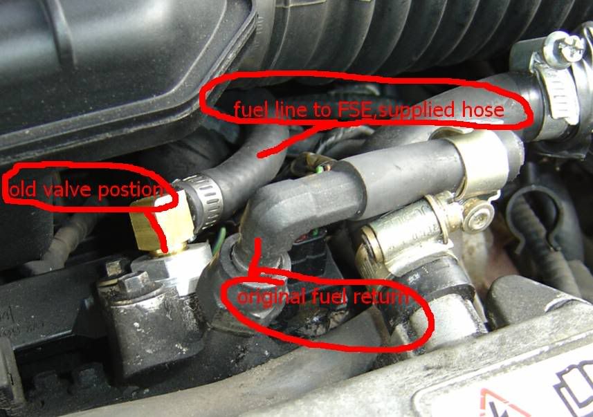
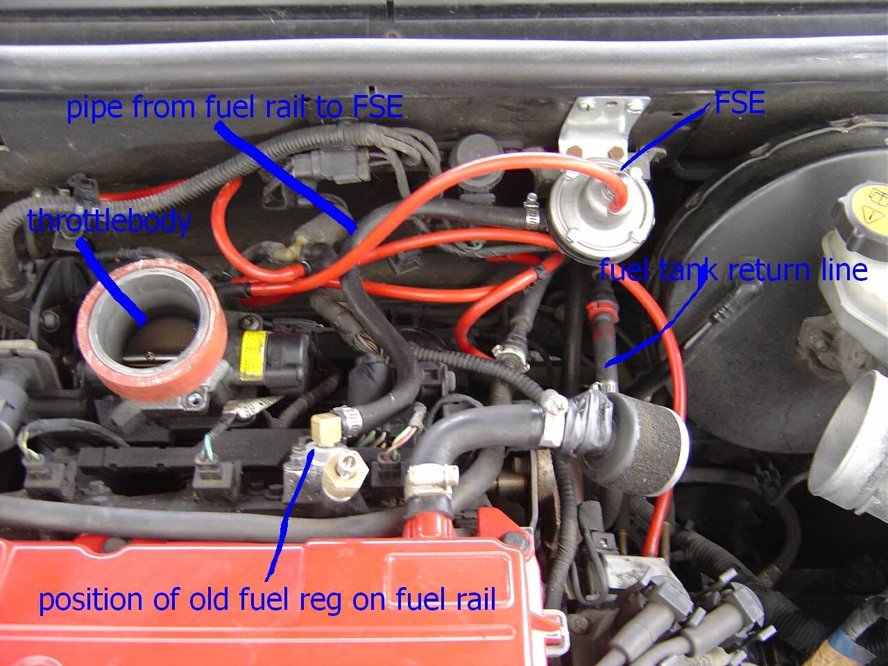
2. Original regulator is located on the top of the fuel rail, remove the small vacuum pipe from the top.
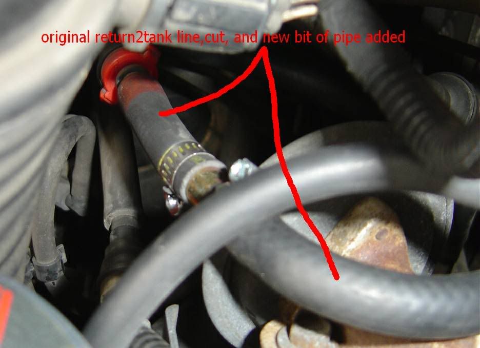
3. Remove the return to tank pipe from its original location.
4. Undo the original regulator from the fuel rail and remove(3 small bolts)
5. NEW ADAPTOR fit in place of the old regulator making sure not to damage the new seals.
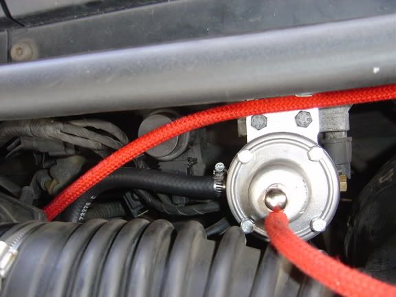
10. The basic installation is now complete( DO NOT start the engine)
11. Recheck all the new connections you have made, ensuring all clips are tight and no hoses are bent or near any heat source.
12. Remove all equipment/tools from your work area.
13. Start the engine and check that there are no leaks from the new connections, let the engine run for 10 mins still checking for leaks.
14. If you are satisfied with your work the vehicle is now ready for testing/tuning of the valve.
THE PROCEDURE SUGGESTED ABOVE IS THE ONE SUPPLIED BY THE MANUFACTURER AND IS FOR GUIDANCE ONLY
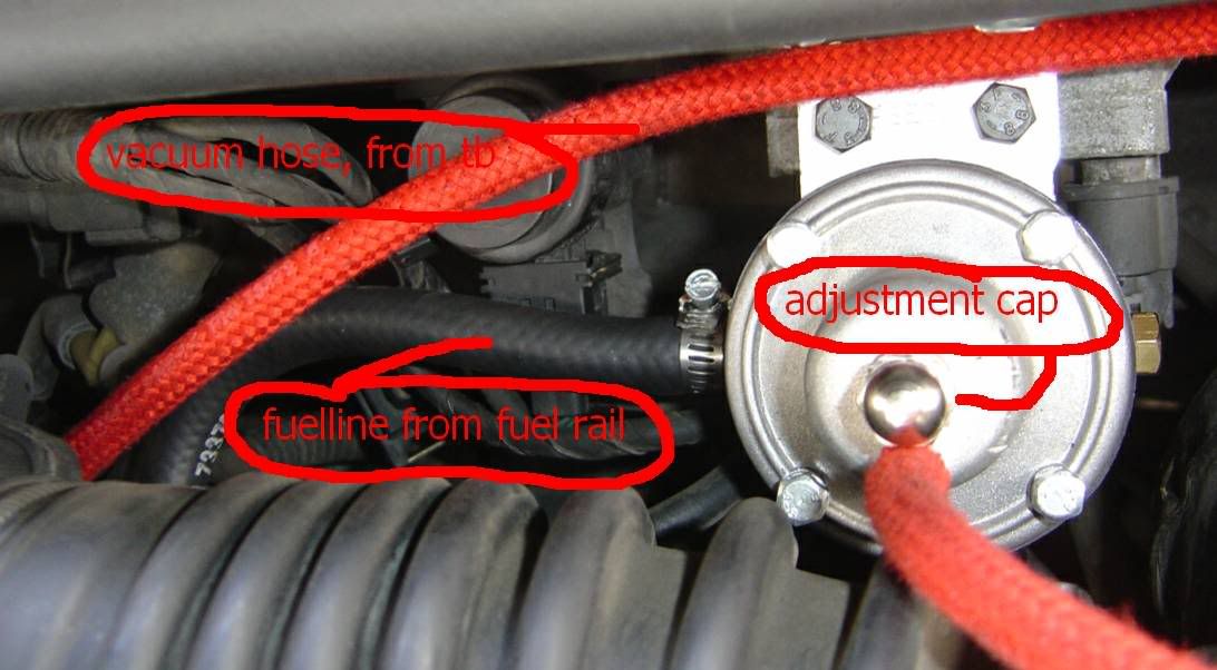
THE ADJUSTMENT TUNING STAGE.
TUNING TO SUIT ENGINE. Note this stage is not always necessary
A small adjustment of the valve regulating screw may be necessary to provide an improvement.
ADJUSTMENT PROCEDURE
WITH THE ENGINE TURNED OFF!
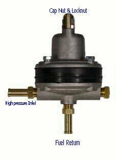
Remove the chromed domed lock nut Slacken locknut around the adjustment screw Turn adjustment screw clockwise 1/4 turn (to enrich mixture) Insome cases a second 1/4 turn adjustment clockwise will be necessary (on 5% of valves fitted an anti-clockwise adjustment of the screw will be necessary) Tighten adjuster screw. Ensure that all tools have been removed from the working area: Start Engine. Road test the vehicle and check your improvement
Your final adjustment may NOT need a full 1/4 turn movement. It is unusal that you will need to adjust the valve more than this amount
CAUTION OVER ADJUSTMENT (CLOCKWISE) WILL RESULT IN THE FUEL PUMP & LINES OPERATING UNDER EXTREME PRESSURE
This above set up works very well, you can then check it with an anologue tyre inflation gauge pushed onto the Valve at the end of the fuel rail, and with the engine running and the vacuun pipe OFF the FSE you should have a pressure of 2.1Bar.
Submitted by arabianjules
 Your Privacy Choices
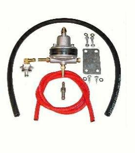