Registrations
We now manually approve all new user accounts due to a large influx of spam bots. Accounts are normally approved within 48 hours.
If you need any help with using this Wiki, please ask here: TalkFord.com Wiki Submission Forum
Difference between revisions of "Electronic Automatic Temperature Control ( EATC ) Retrofit"
Compuwiz uk (Talk | contribs) (→Option 3) |
Compuwiz uk (Talk | contribs) |
||
| Line 6: | Line 6: | ||
== Required Parts == | == Required Parts == | ||
| − | EATC Control Unit | + | ''Here is the Full list of parts that are required, depending on which route you choose to go for will then depend on just what items you need.'' |
| − | Interior Temperature Sensor | + | |
| − | EATC Fan Motor | + | |
| − | Sunload Sensor | + | EATC Control Unit. |
| + | |||
| + | Interior Temperature Sensor. | ||
| + | |||
| + | EATC Fan Motor. | ||
| + | |||
| + | Sunload Sensor. | ||
| + | |||
New Dashtop Airvent Grill to accept the new Sunload sensor ( your old grill can be suitably modified if your handy with a drill ) | New Dashtop Airvent Grill to accept the new Sunload sensor ( your old grill can be suitably modified if your handy with a drill ) | ||
| Line 38: | Line 45: | ||
[[Image:Parts.jpg]] | [[Image:Parts.jpg]] | ||
| + | [[Image:Vent.jpg]] | ||
== Method == | == Method == | ||
| Line 94: | Line 102: | ||
Climate Motor Pin 5 - Control Unit Black Plug Pin 1 ( replacing the wire already inplace - this wire can either be cut out & the new wire attached to the bit left in the black plug or removed & taped up safely & then the new pin fitted in its place ) | Climate Motor Pin 5 - Control Unit Black Plug Pin 1 ( replacing the wire already inplace - this wire can either be cut out & the new wire attached to the bit left in the black plug or removed & taped up safely & then the new pin fitted in its place ) | ||
| + | |||
| + | |||
| + | [[Image:Fan_Motor_Wiring.jpg]] | ||
| + | |||
| + | the wiring should look something like This ( this piccy is minus the Pin 1 Power Feed As Thats Still On The Car ) | ||
| Line 113: | Line 126: | ||
Interior Temp Sensor Pin 4 - Pin 2 White plug on the control panel | Interior Temp Sensor Pin 4 - Pin 2 White plug on the control panel | ||
| + | |||
| + | |||
| + | [[Image:Sensor_Wiring.jpg]] | ||
| + | |||
| + | The Wiring Should Look Similar To This | ||
[[Image:Fusebox_Power.jpg]] | [[Image:Fusebox_Power.jpg]] | ||
| + | |||
'''The Control Panel''' | '''The Control Panel''' | ||
| Line 132: | Line 151: | ||
How-to taken from forum user [http://www.fordmondeo.org/forum/showuser.php?uid/18329/ Taffiboy ] | How-to taken from forum user [http://www.fordmondeo.org/forum/showuser.php?uid/18329/ Taffiboy ] | ||
| − | Some minor additions by Compuwiz_uk | + | Some minor additions & Pictures by Compuwiz_uk |
[[Category:Electrical]] | [[Category:Electrical]] | ||
[[Category:Mk3]] | [[Category:Mk3]] | ||
[[Category:Tips]] | [[Category:Tips]] | ||
Revision as of 18:16, 25 September 2008
Contents
Note
this guide is still in the making at the minute so is not a full guide just yet but more info will be added when i get a minute.
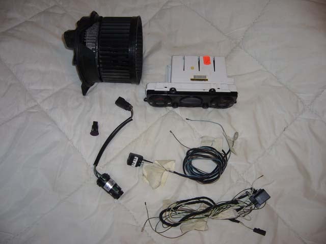
Required Parts
Here is the Full list of parts that are required, depending on which route you choose to go for will then depend on just what items you need.
EATC Control Unit.
Interior Temperature Sensor.
EATC Fan Motor.
Sunload Sensor.
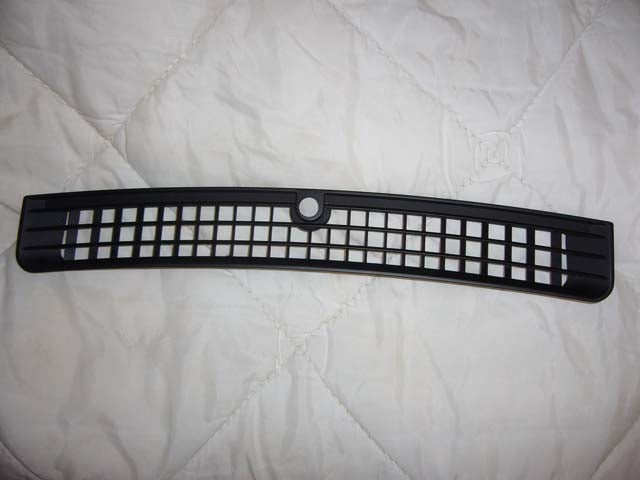
New Dashtop Airvent Grill to accept the new Sunload sensor ( your old grill can be suitably modified if your handy with a drill )
Wiring ( preferably removed from a complete ghia/ghia x dashboard loom but if not then a selection of ends with some wiring will do but will require lots of joins to be made instead of just 1 like a complete loom will require )
if your going the plugs only route you will need :-
EATC control unit plug with wires ( either plug as the pins inside are the same ( require 6 wires/connectors from inside it )
EATC fan motor plug with wires ( remove the connector @ pin 1 ready to accept the lead from pin 1 of your current motors connector ( leaves the other 3 wires in the plug nice & tidy & means a much easier job )
Interior Temperature Sensor connector plug to connect the temperature sensor to the EATC control unit
Sunload Sensor Plug to also connect this upto the EATC control unit
Lowest Green Fusebox Plug for one of its connections ( to power the interior temperature sensor )
if your going the full wiring loom route your will require :-
ghia/ghia x dash loom from which you will need the following :-
Fan motor wiring ( earth lead & 2 wires to the control unit - the 4th wire can simply be removed from the plug very easily )
Temperature & sunload sensor wiiring ( this is a the one that may take the longest to remove as 1 wire goes all the way to the fusebox & its also joined to a 3rd sensor which is already inplace on your car ( this 3rd sensor will need to be cut off ( one wire ) from the other sensors but make sure you leave enough wire to easily connect the wire from the car at the minute to it later )
( its also worth marking the wires locations as you remove them for easier refitting later ( make sure your cutting off the correct sensor wire too as the sunload & the sensor wiring your cutting off have the same kinda plug & the wiring colours are almost identical too, but the wiring is reversed at the plug ( this can easily be reversed if you do make a boo-boo though )
Method
There are 3 levels of upgrade:
Option 1
Getting The Look but not the full function.
The manual knobs can be directly replaced for the digital unit no wiring changes required, this gives you a quick "sexy looking dash" - the digital unit will work for temp control, air direction, aircon on/off and recirc. However, the fan speed has to be set using the manual knob and this knob left behind the dash after reassembly.
Option 2
Installing an auto fan too.
This has four connections running to it. Green / Red (or) Brown power this already exists in manual aircon cars it can be used to power the auto fan. Black (earth) -just earth this to a suitable point under the dash. Brown/Blue connection which goes to the No 1 connection on Black socket on the back of the Digital Control unit. Blue / White connection which goes to No3 connection of the same socket.
(On Manual Aircon cars, Connection No1 will have a black / white running to it just cut this off and connect the brown / blue wire).
You can leave the manual fan speed switch behind the dash as it is redundant now.
Both the white and black harness sockets for the control unit can be easily taken apart by sliding the end cap off an then removing the plug with cables, you need a bionic eye here but the holes have been numbered in each corner.
When this modifcation is completed you should have a fully working (manual) digital control unit - all functions except the Auto.
Option 3
The Full Retrofit.
There are 2 additional sensors, the sunload sensor which fits into the screen demister vent. This vent will need to be removed as you need to drill a hole (same diameter as the sun load sensor - about 12mm) in the circular blank.
The most awkward part I found was running the sunload sensor cables (2 of them) through to the control unit. In the end I removed the speedo housing and drilled a 5mm hole into the demister vent under the dash and fed the cables through - BE CAREFUL HERE NOT TO DRILL INTO AND THROUGH THE TOP TRIM OF YOUR DASH.
The interior motorised sensor will clip into a recess under the drivers trim to the left of the steering wheel - you will see a slotted vent about the size of a 10 pence piece.
Once this has been done you can re-assemble everything as I was able to work with just the radio removed.
The motorised sensor has four cables one of which is power that is fed to the fuse box.
the wiring connections for the full retro-fit are as follows :-
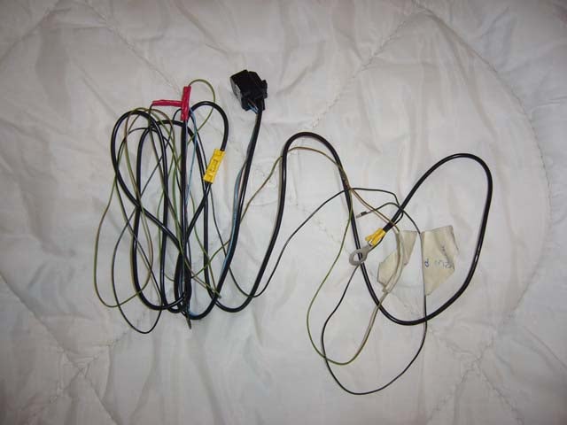
The Blower Motor
Climate Motor Pin 1 - Feed From Normal Heater Motor Pin 1 ( Green/red stripe ) ( can be simply removed from the old plug & widened by 2mm or so to fit into the new motors plug )
Climate Motor Pin 2 - To a suitable ground ( needs to be a sturdy ground )
Climate motor Pin 4 - Control Unit Black Plug Pin 3
Climate Motor Pin 5 - Control Unit Black Plug Pin 1 ( replacing the wire already inplace - this wire can either be cut out & the new wire attached to the bit left in the black plug or removed & taped up safely & then the new pin fitted in its place )
the wiring should look something like This ( this piccy is minus the Pin 1 Power Feed As Thats Still On The Car )
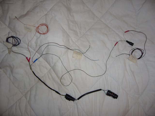
The Sensors
Special Note
Control Panel Black Plug Pin 16 Provides a common power feed for all the sensors used to monito the climate & is already inplace on the car so will either need tapping into for the 2 new sensors or it will need removing & replacing with your own mini loom for the sensors & then the removed pin connecting upto the mini loom ( whichever way you find best really )
Sunload Sensor Pin 1 - Pin 16 Black plug on the control panel ( common power )
Sunload Sensor Pin 2 - Pin 18 White plug on the control panel
Interior Temp Sensor Pin 2 - Pin 16 Black plug on the control panel ( common power )
Interior Temp Sensor Pin 1 - Pin 16 White plug on the control panel
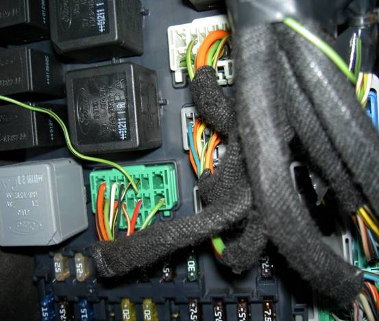
Interior Temp Sensor Pin 3 - Pin 10 of C501 of the fusebox ( see following piccy to see where that is - look for the single wire on the green plug )
Interior Temp Sensor Pin 4 - Pin 2 White plug on the control panel
The Wiring Should Look Similar To This
The Control Panel
with the above done the wiring is complete, you just need to tuck the old manual motor speed wiring plug out of the way & re-assemble the car & you should be sorted.
Things To be Aware of & checks to make
Mine is still all working well - the temp inside the car is being maintained and as a quick check once all the wiring is complete if you turn the temp up full the fan will slowly speed up and then once the desired temp is achieved will slow down. (there is a slight delay - say 10 seconds). Once you have the auto working and select it none of the indicator lights on the EATC control unit will light up (not even the Aircon one) as the unit is doing it all automatically) - your aircon will kick in and out automatically. Obviously all this can be manually overridden by selecting your own settings (the indicator lights will then illuminate your desired settings).
Another check is when you select screen the auto fan should come in on high (aircon on although the light will not come on)and all air directed to the screen.
How-to taken from forum user Taffiboy
Some minor additions & Pictures by Compuwiz_uk
 Your Privacy Choices