Registrations
We now manually approve all new user accounts due to a large influx of spam bots. Accounts are normally approved within 48 hours.
If you need any help with using this Wiki, please ask here: TalkFord.com Wiki Submission Forum
Touchscreen Sat Nav Facelift - Retro Fitting
For more information, visit the Ford Mondeo forum on TalkFord.com, the definitive resource site covering all Fords from the present day to the 1970's.
|
Overview Guide | |
| Ford Model: | Mondeo |
|---|---|
| Petrol/Diesel: | Both |
| Estimated Cost: | £400 plus |
| Difficulty? | Medium to Hard |
| How long does this take? | A Good Weekend |
Contents
- 1 Overview
- 2 Features
- 3 Tools required (from memory)
- 4 Full Parts List
- 5 Breakdown of Parts Shown
- 6 Centre Console Removal
- 7 Installation of "New" parts
- 8 Pin Connection at the back of the Radio Unit
- 9 Problems found
- 10 Time to complete the works
- 11 Fitting into your car
Overview
This guide is to retrofit the Denso touch screen navigation unit to a facelift MK3, it is possible to fit the unit to a non facelift car and there is a guide to doing this elsewhere in the workshop wiki's. It is fairly straightforward with a small amount of wiring/ crimping to do and a lot of dashboard & interior dismantling and running of cables. The unit also controls the radio, CD changer and climate control.
First thing is to gather together all the necessary parts, everything is needed otherwise the installation cannot be totally completed so make sure you order all the bits from a breaker or strip them all out of the donor vehicle.
When I first looked into this there where a couple of issues that I thought might have caused problems:
1. Can bus (controller area network) wiring, this is the system that transmits signals from the cars ECU etc around the cars components, the sat nav unit, for example, needs to know the cars speed and this is done via the can bus wiring. The good news is that facelift cars have the can bus system and it is wired up to the existing stereo so it is not an issue.
2. Head unit Vin code security, according to the Ford literature head units are coded to the vin number of the original car and will not work in another vehicle, again this was not an issue, the unit worked fine with just the normal 4 digit security code in-putted.
Features
The Ford DVD navigation system with touchscreen has the following special features:
7" colour touchscreen (16:9)
external navigation computer with DVD drive
navigation DVD for Western Europe
The road name is entered before selecting the destination town/city in order to speed up the route selection.
fast calculation of the route
Traffic Message Channel (TMC)
integrated audio unit (Sony)
MP3-compatible CD player
integrated controls for the automatic air conditioning
4 x 20 W output power
connection for external CD changer
connection provided for Rear Car Entertainment System for the rear seats
connection provided for handsfree telephone system
From 2004.50: connection provided for Bluetooth (cableless data transmissions)
Tools required (from memory)
4x head unit removal pins
T20 Torx Bit
T25 Torx Bit
Philips/cross head screwdriver
8mm Socket
10mm Socket
Long extension bar for socket
T-bar/ratchet for socket.
Wire Cutters
Crimping Tools
Lots & lots of male & female (insulated) crimps (Alternative to crimps is soldering iron & solder with plenty of heat shrink tubing or insulating tape)
Full Parts List
Main Head Unit with security code.
Cd Changer with cassette unit
DVD drive with map disk
mounting brackets for the above 2 drive units
Boot trim for the drive side of the boot
Drive Cover Trim Panel
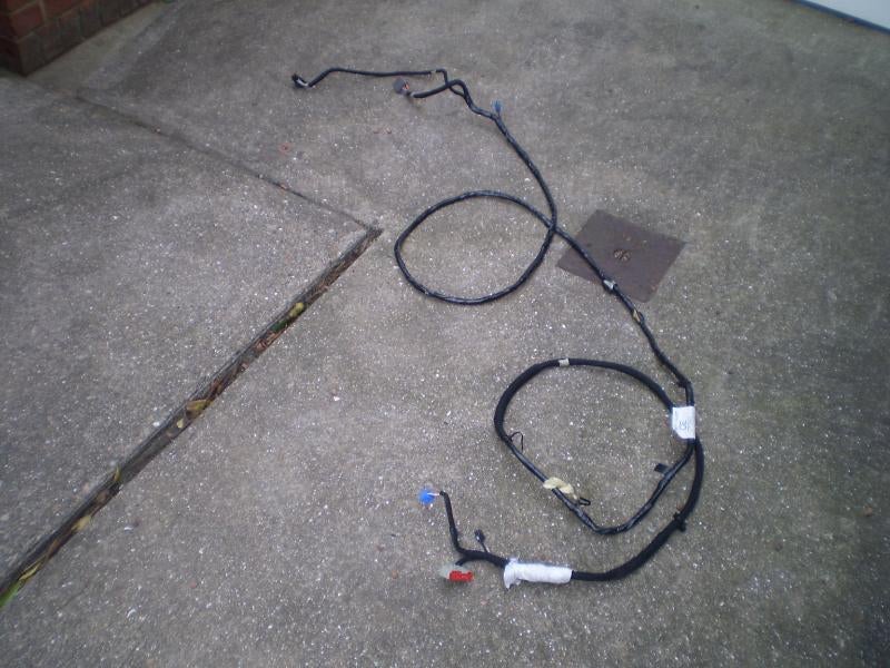
Main loom from front to rear drive units
Front GPS Antenna Base
Front Main Antenna Section (this differs to the standard antenna connection)
Front Antenna Wiring
Small loom to connect head unit, changer to main dash loom
A Decent Length of the Donor Vehicles Dashboard Loom that the small loom connects to (makes the connection process easier to reverse should you ever want to)
Clock Surround Trim Panel, (as the normal one is about 5mm short.)
Main Dash Centre Console Panel
Other items (not essential to operation but needed to get maximum use out of your new unit)
Rear Radio Antenna Wiring to roof panel
Rear Antenna Wiring from roof panel to rear window connection point
Antenna Roof Mounted Connection plate (holds the 2 halves of the wiring in place in the roof panel)
If possible the head unit & both rear drive units need to be from the same donor vehicle otherwise you will have problems and will have to go to Ford to sort out the connection problems you will have getting the units talking to each other. If you have to take this all out at the wreakers it will take you about 3hrs ish to do for all the bits.
Ford Prices & Part No's for the items needed
If you are picking the bits up make sure you have all the above, if you don’t it’s going to be expensive at the dealer/stealers just to replace the missing bits. Just to give you an idea of the cost (in Euro's) here is a quick breakdown of the parts:
Map Disk - 1685392 - €305.43
Nav Computer/DVD - 1451000 - €2347.27
Head Unit Display Only - 1342520 - €2757.19
Antenna Mast - 1123963 - €19.34
Antenna Base - 1508610 - €68.32
Antenna Cable - 1317244 - €106.46
Radio/CD unit Only - 1445682 - €966.97
CD Autochanger - 1364230 - €430.04
CD Magazine - 4058064 - €74.39
Diversity Antenna Cable - 1349620 - €28.06
Head Unit Wiring Loom with rear Ent, Sys. - 1338453 - €178.08
Cable for Rear Ent Unit - 1338097 - €72.04
Rear Ent System - 1347838 - €237.45
Centre console for Touchscreen Sat Nav - 1327410 - €285.01
Top Trim Panel fot Nav system - 1256683 - €62.48
Boot Trim - 1257373 - €167.99
CD Changer/Nav Comp Cover - 1309549 - €62.55
EATC Unit for Touchscreen system - 1365750 - €249.42
CD Changer Brackets (LH) - 1307163 - €53.31
CD Changer Brackets (RH) - 1307165 - €48.47
Front to rear Loom - 1317344 - €106.46
With the prices listed you are looking at the best part of €8000 just to buy the parts from Ford. That's why you need to make sure that you have everything from the donor car 1st time. Use the above as a check list if you are buy a kit from the salvage yard/ebay as they might have already remove the items from the car, that they is all of the parts there, otherwise look else where or talk the price down.
Prices on ebay can be anything from £350 upwards, but on average expect to pay about £450 to £500. The last two set I have seen when for £610 and £441. The £610 was already out of the car and the pictures shown, seen to have some of the parts missing, the other at £441 you had to remove all of the wiring out of the car yourself, which was the better deal. As you got to see where all of the parts fitted so you were able to refit back into your own car.
Breakdown of Parts Shown
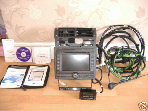
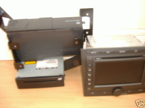
1. Touchscreen head unit with code (the unit is actually 3 separate components, the touch screen unit itself and screwed to the back are the climate control and navigation modules, unless you are buying everything new (doubtful as the touchscreen unit itself is over £1700 new!) these should all come together as one unit.
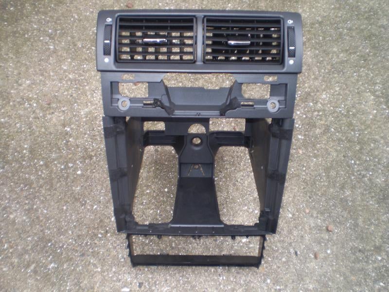
2. Dash centre section, this comes as one large piece including the airvents, the nav unit dash centre section is completely different to the ones for the standard stereos.
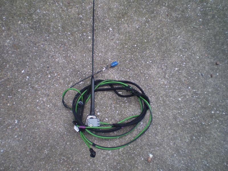
3. Sat nav aerial base, antenna and wiring leads.
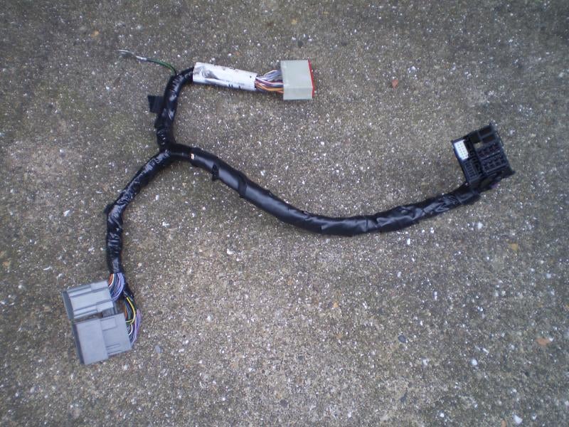
4. Sat nav dashboard section wiring loom.
5. Headunit to CD changer/ DVD drive wiring loom.
6. Boot mounted sat nav DVD drive.
7. Boot mounted 6 disc CD changer.
8. 2 x brackets to secure the DVD and CD changers, these are different for a hatch, saloon and estate.
9. Trim piece/ cover to fit over the DVD drive and CD changer, again these are different for a hatch, saloon and estate.
10. Software CD and Map CD.
11. New clock surround, the ones in sat nav equipped cars are about 5mm deeper, you can get away without this as described later.
Centre Console Removal
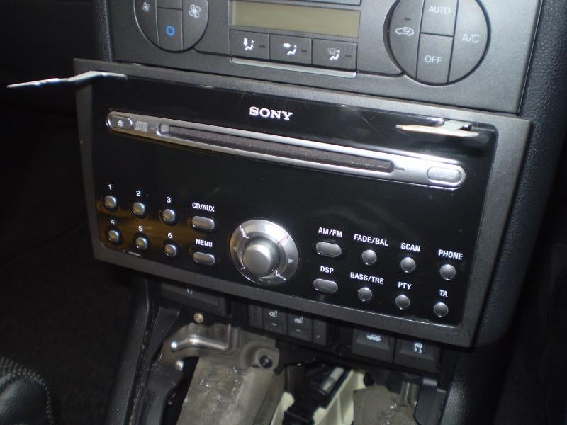
First thing to do is to remove the old stereo, get some of the correct removal keys (Halfords, Ebay etc) and remove it, the unit in my car was the Sony 6CD unit. Unplug the quadlock wiring plug and aerial lead as the stereo comes out.
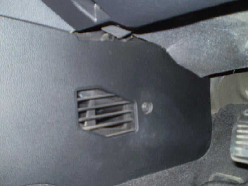
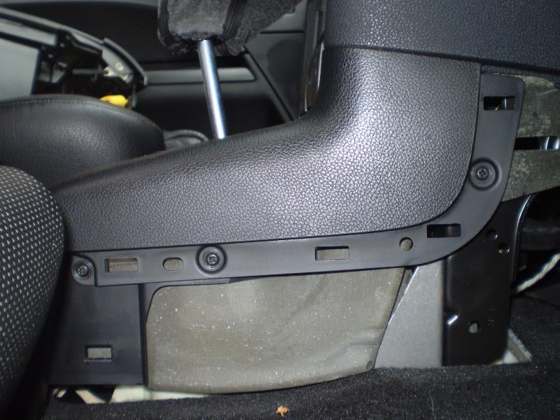
Now remove the centre console/ footwell side trims, there is one screw in the footwell then the trim is just pulled away to release the securing clips.
This then exposes the side securing screws for the centre console gearstick surround, remove these from both sides.
Remove the gearlever surround by gently levering it out, it is held in by securing clips only, the gear lever gaiter can remain on the gearstick.
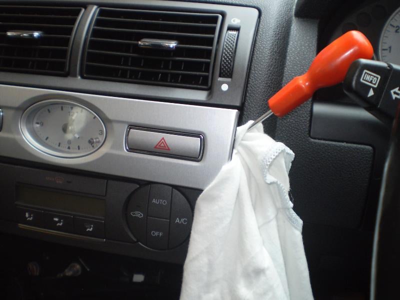
Remove the clock/ switches surround, again by gently levering it out.
Remove the cupholder (3 screws), heated seats switch (if fitted) and boot release/ ESP switches and also the one screw above this switch.
Now remove the metal bracket that secures the centre console to the dash console.
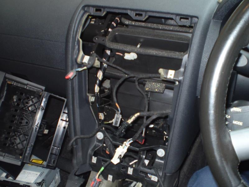
The centre dash section can now come out, it is held in by 2 screws where the clock surround was removed, 4 screws on the inside sides where the stereo was and two long screws at the bottom edge, disconnect the two wiring plugs in the back of the climate control unit as it comes out, the plugs have a locking lever that needs to be unlatched before they will come out.
Remove the centre console by undoing the 3 8mm bolts in the armrest storage compartment and one screw accessed when the cupholder/ ashtray has been levered out, now pull the handbrake right up and lift the centre console out.
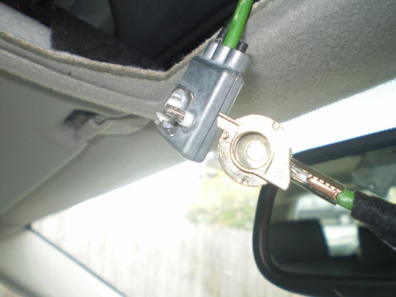
Now remove the front interior light and undo the aerial securing screw, remove the aerial.
Remove the drivers sunvisor (this makes running the aerial wire easier)
Remove the drivers side window pillar trim, it is held on by 3 clips and comes off with some gentle levering.
Remove the drivers side lower dash trim, open the storage drawer and undo the two screws in there and the three along the bottom of the trim, it then comes off with a pull to release the two remaining securing clips, then unclip the cabin temperature sensor and remove the trim, this lower dash trim is removed to allow the new aerial lead to be ran in.
Installation of "New" parts
Ok, now we can start fitting new bits, install the new centre dash section.
Run the new aerial wire along the roof, down the windscreen pillar then under the drivers side dash to the back of where the stereo will go, I just coiled the old aerial wire up and secured it under the dash. The pic below shows the difference between the normal aerial lead and the sat nav one (on the left).
Fit the screw through the wiring connector and fit the new aerial, once this is done you can refit the interior light, sunvisor, windscreen pillar trim and drivers side lower dash.
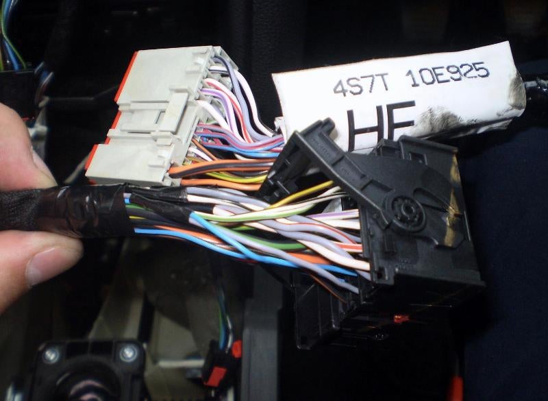
Now we come to the wiring bit, the problem is that from the factory cars equipped with sat nav have a different dashboard wiring loom with an extra connector (C38) into which the sat nav headunit wiring loom can be plugged into. We need to somehow join the two incompatible connectors as shown below, the cars existing wiring terminates in the black quadlock connector but we need to connect this to the grey plug of the sat nav loom.
It is possible to buy a quadlock adaptor so that you could leave the cars wiring intact and only have to cut off the grey plug of the headunit wiring loom, however I will be leaving the sat nav install in the car permanently so the simple way is to just chop the two connectors off.
So battery disconnected both wiring plugs are cut off.
The wiring of the two looms together is reasonably straight forward as many of the wires are the same colour for the same duty in both looms, the sat nav install only requires two new extra wires to be connected – a feed from the reverse lights circuit which the sat nav uses to know when the car is reversing and an extra live (when the key is in position 1) for the CD changer/ DVD drive in the boot. For the reverse live I ran an extra wire to the boot area with the main CD changer/ DVD drive loom and picked up the reverse light wire at the light cluster, I did this as it was the easiest option, you can also pick the reverse signal up at the wiring loom in the passenger footwell if you prefer. For the extra power I just piggybacked it with the live (when key at position 1) already in the loom.
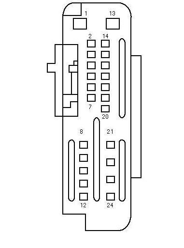
Details of the wiring pins on the C38 connector and the compatibility with the existing wiring in the cars quadlock connector are as below, use crimps, solder etc to connect the wires together.
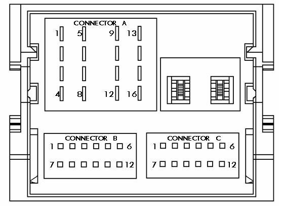
Pin Connection at the back of the Radio Unit
Connector A (C517/C518)
Speakers (C517)
Pin 1 Right Rear +
Pin 2 Right Front +
Pin 3 Left Front +
Pin 4 Left Rear +
Pin 5 Right Rear –
Pin 6 Right Front –
Pin 7 Left Front –
Pin 8 Left Rear –
Power (C518)
Pin 9 CAN +
Pin 10 CAN –
Pin 11 Keycode Ground
Pin 12 Ground
Pin 13 Alarm Sense (From GEM)
Pin 14 Illumination
Pin 15 Battery + (From F72)
Pin 16 Ign. Sense (Accessory) (From F69)
Connector B (C520)
Pin 1 Mono +
Pin 2 Sw A+ (Switched Output (On when stereo is on) - Used with Rear Seat DVD's)
Pin 3 Aux L+ (CD Changer)
Pin 4 Aux R + (CD Changer)
Pin 5 PTA (Phone Mute)
Pin 6 SWC (Steering Wheel Controls)
Pin 7 Mono -
Pin 8 SWC Gnd (Steering Wheel Controls)
Pin 9 Aux L – (CD Changer)
Pin 10 Aux R – (CD Changer)
Pin 11 Rev Sense (Used for Navigation)
Pin 12 AVC
Connector C (C519)
Pin 1 RSE L+ (Rear Seat Entertainment)
Pin 2 RSE R+ (Rear Seat Entertainment)
Pin 3 Mono 2 +
Pin 4 Sub W +
Pin 5 Aux 2 L (Glovebox Aux Socket L)
Pin 6 Audio Gnd
Pin 7 RSE L – (Rear Seat Entertainment)
Pin 8 RSE R – (Rear Seat Entertainment)
Pin 9 Mono 2 –
Pin 10 Sub W –
Pin 11 Aux 2 R (Glovebox Aux Socket R)
Pin 12 Mic.
C38 Connector
Pin 1. Orange/ black – Fuse 72 (20 Amp) permanent live, this wire is also in the quadlock connector and is the same colour so just join the two together.
Pin 2. Yellow/ green – fuse 69 (7.5 Amp) Live when key turned to position 1, this wire is also in the quadlock connector and is the same colour so just join the two together.
Pin 3. Brown/ yellow – To Pin 2 of remote unit on steering column, this wire is also in the quadlock connector and is the same colour so just join the two together.
Pin 4. White/ black – To Pin 1 of remote unit on steering column, this wire is also in the quadlock connector and is the same colour so just join the two together.
Pin 5. Black/ orange – To pin 10 of gem module, this wire is also in the quadlock connector and is the same colour so just join the two together.
Pin 6. Blue/ red – Can bus negative, this wire is also in the quadlock connector but is a solid blue colour, it also needs pin 18 connecting to it to link the extra can bus for the CD changer/ DVD drive.
Pin 7. Grey/ red Can bus positive, this wire is also in the quadlock connector but is a solid grey colour, it also needs pin 18 connecting to it to link the extra can bus for the CD changer/ DVD drive.
Pin 8. White – Rear right speaker pin 2, this wire is also in the quadlock connector and is the same colour so just join the two together.
Pin 9. White/ violet – Rear left speaker pin 2, this wire is also in the quadlock connector and is the same colour so just join the two together.
Pin 10. White/ red – Front right speaker pin 2, this wire is also in the quadlock connector and is the same colour so just join the two together.
Pin 11. White/ black – Front left speaker pin 2, this wire is also in the quadlock connector and is the same colour so just join the two together.
Pin 12. Grey/ black – Front left speaker pin 1, this wire is also in the quadlock connector and is the same colour so just join the two together.
Pin 13. Orange/ green – Fuse 71 (10 amp) Live when ignition key turned to position 1, there is no equivalent wire in the quadlock connector, link it together with Pin 2 to provide the switched power feed to the CD changer/ DVD unit. If you want to use the changer in the "one hour" mode and to be able to remember where it was from last time you can connect this to Pin 1.
Pin 14. Black/ blue – Light switch pulse width module pin 9, this wire is also in the quadlock connector and is the same colour so just join the two together.
Pin 15. White/ red – Aux in unit pin 4, this wire is also in the quadlock connector and is the same colour so just join the two together. Pin 16. Grey/ red – Aux in unit pin 1, this wire is also in the quadlock connector and is the same colour so just join the two together.
Pin 17. Black – Aux in unit pin 3, this wire is also in the quadlock connector and is the same colour so just join the two together.
Pin 18. Blue/ red – Can bus negative, link to pin 6.
Pin 19. Grey/ red – Can bus positive, link to pin 7.
Pin 20. Green/ white – to reverse switch, run in a reverse live feed as described above.
Pin 21. Grey – Rear right speaker pin 1, this wire is also in the quadlock connector and is the same colour so just join the two together.
Pin 22. Grey/ white – Rear left speaker pin 1, this wire is also in the quadlock connector and is the same colour so just join the two together.
Pin 23. Grey/ red – Front right speaker pin 1, this wire is also in the quadlock connector and is the same colour so just join the two together (Note that although this is the same colour wire as pin 19 it is a larger diameter/ gauge wire).
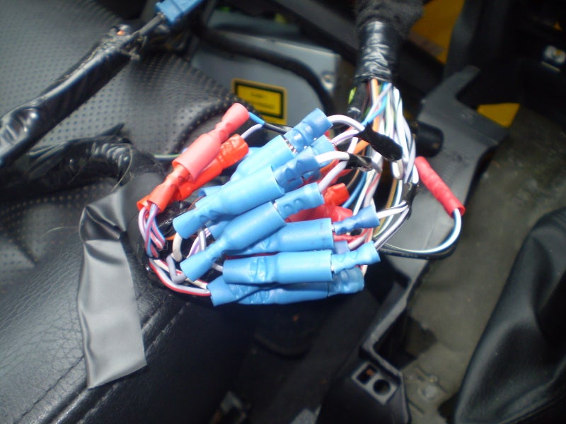
Ok, now the wiring is done you should be left with something like below
I then taped it all up and secured the ‘new’ loom with tie wraps.
Now feed the wiring back into the centre dash area, there is plenty of room under the centre dash to house the new wiring loom and extra connectors.
Plug the aerial lead and the quadlock connector into the back of the sat nav unit, you may notice an extra aerial connection, this is for the ‘diversity’ aerial, this was an extra aerial built into the rear window and the headunit could select between the two for the strongest signal, it is for the radio only not the sat nav, my car did not have the extra aerial installed so I did not fit the extra lead and the unit still works fine. Now plug the connector on the front to rear wiring loom into the nav unit on the back of the headunit.
Slide the headunit into the dash connecting the climate control wiring plugs as you refit it.
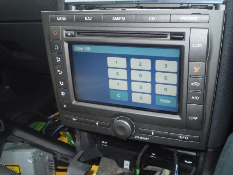
Now reconnect the battery and switch the unit on, if everything has gone ok you should see this.
Enter the security code then switch the unit off and continue the install.
Images of Common Install for all models
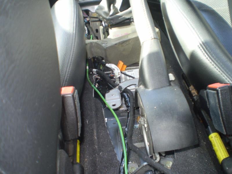
Run the front to rear wiring loom to the boot area. The correct route is along the centre tunnel across under the passenger seat then along the cill over the rear wheelarch and into the boot area.
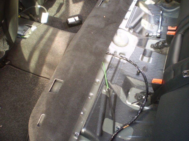
I decided to do it the easier way (to avoid having to remove the passenger seat) of just running it under the centre console along the top of the centre tunnel, under the rear seat and over the wheelarch into the boot. Where the loom runs on top of the centre tunnel I unwrapped the outer tape from the loom and flattened the wires out so that they would not cause the carpet to stick up, in the finished install there is no evidence of the wiring.
Run the front to rear loom along where the centre console sits, avoid the handbrake area and secure the loom with tie wraps.
Run the ‘flattened’ loom under the carpet on top of the centre tunnel and through to underneath where the back seat sits.
Now feed the wires under the trim up over the wheelarch and behind the trim into the boot area.
Images of Estate Install
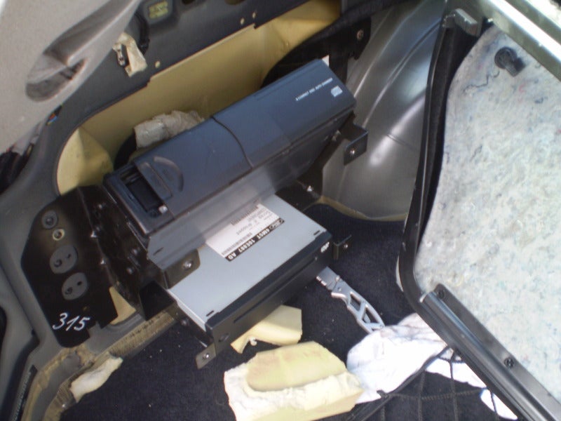
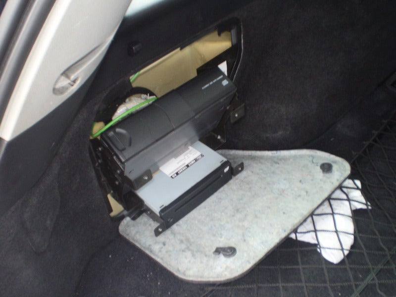
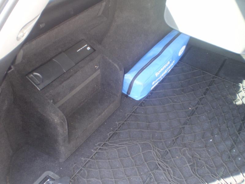
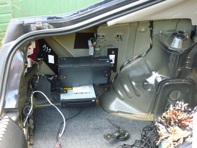
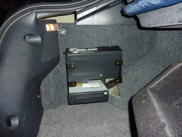
Mount the CD changer and DVD unit on their brackets and secure the brackets to the pre-drilled holes in the left hand side boot area, I used self tapping screws and speedclips, plug the wiring plugs into the CD changer and DVD unit, the DVD unit also needs the black aerial lead plugging into it.
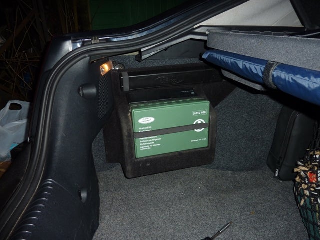
On my estate I just needed to trim a small amount of the sound deadening foam away and did not need to cut the carpet trim at all as the units sat handily exactly where the first aid kit flap is.
Power the headunit back up and press the eject button on the DVD unit, if the map disk isn’t in there insert it now. We next need to fit the trim piece over the units, the one I had was from a hatchback and needed a bit of cutting and adjustment to make it fit but the final result is ok, I also had to remove the existing access flap by cutting it off.
Ok, we have finished in the boot.
Images of Rear Seat Entertainment Unit Install
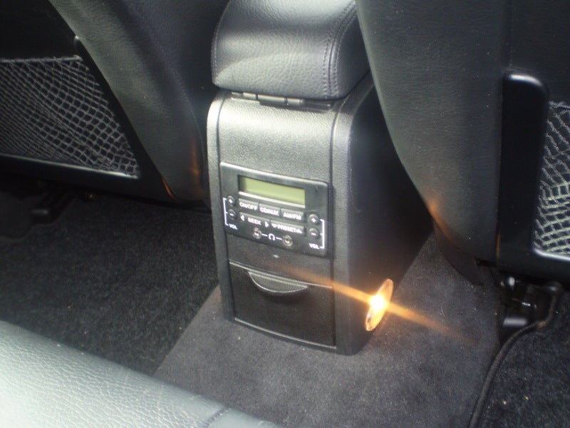
The set up I bought came with the rear seat entertainment unit which was an option so you may not have it, if you want to retrofit it at a later date there is a guide elsewhere in the workshop wikis.
To fit it I needed to cut a hole in the back of the centre console then the unit just plugs into the headunit loom, while I was there I took the opportunity to fit some rear footwell lights, I used some Ford Galaxy footwell lights as the oval shape is a bit different.
Check the wiring loom is secure and routed ok where the centre console sits and then refit the centre console.
Images of Completed Install
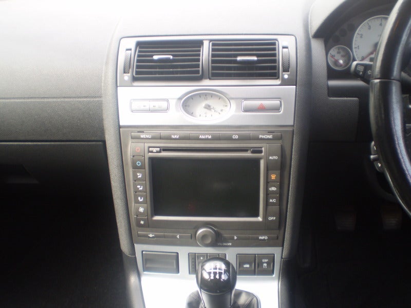
Now refit all the remaining parts, the gearlever surround, side trims, cup holder, switches, clock surround etc etc and that’s it done.
As mentioned earlier the correct clock surround for sat nav equipped cars is a about 5mm deeper than a standard one, rather than buy a new one from Ford I just used a piece of foam trim tape to fill the gap and I think it looks ok.
Images of Hatchback Install
CD Changer/DVD mount in the Hatch, saloon's maybe very similar install.
To mount the unit on to the hatch, you will need to remove the rear light cluster to gain access to the mount point.
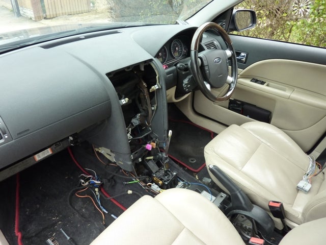
Dash in bits, as you can see you really need to take it apart to fit.
Completed Install without cover
Completed Install with cover
Head Unit in Action
Problems found
Fitting the 2nd aerial can be a problem, due to the limited space involved for threading the extra cable through from the roof panel into the boot hatch to the rear window, it also involves taking apart quite a bit of trim to be able to route the cable correctly to the front. This is from the radio, up the LH a pillar, into the roof space towards the rear near the C pillar. Here it will connect to the socket which comes from the rear window cable which you have just installed. It is on the hatch, not too sure about the saloon and the estate.
When connecting up the head unit make sure to do it in the following order
Antenna 1 (& 2 if you have them both)
ETAC unit (black & white plugs)
Nav Unit/screen
Quad lock connection.
Push the head unit back slow making sure that you have enough free space at the back of the cage. (Pulling the loose wiring down out of the way if required) If the unit stops when there about 10mm to go & there is nothing that looks to be causing it then check the dashboard near the top of the radio just behind the trim panel as this may be catching on the top fixing connections of the head unit & preventing the head unit going any further, the problem is resolved by cutting away a small amount of the dash material ( the small bits that the upper screws for the head unit surround fasten into ), once enough material has been cut off ( we are taking 2-3mm’s only so won’t cause any problems for the fastening point etc ) then the head unit will slide into place no problem
If you have the C38 connector from the donor’s car, this will make your life easier if you ever want to go back to std. radio. Patch this into the “old quad lock” cables, most of the cables matches up to the quad lock except the following:
Ground - Can be left electricity safe or taken to ground.
Key code ground - Can be left electricity safe or taken to ground.
Reverse sense - This can be picked up from the C31 Connection Pin 11
Switch feed Pin 13 on the C38 connection, I found that if this was connected to Pin 2 on C38 I was unable to eject the CD cassette in the changer when in the "one hour" mode. Plus the head unit was unable to see the changer. Remade this connection to Pin 1 on C38 so the unit could have a permanent feed, to me the unit was working correctly. The unit work find with a switched feed, but if I had left the unit playing a CD from the boot, it was always reloading the disks and going back to Disk 1, track 1. Plus I had retro fitted the RSE unit and had put this on permanent feed. Since doing this the unit and changer now remembers where it was from last time.
If you have the RSE unit, you might have the socket on the loom already if not you can patch the unit in when your patching in the c38 connection/small patch loom for the head unit, just follow the guide of the retro fit in the wiki. All of the connections are the same.
Once it’s all in & put back together enjoy your work, you have earned it.
Time to complete the works
Removal of parts from donor vehicle (2-4 hours depending on how familiar you are with the stripping of the car & how much of the interior is still present in the car)
Fitting into your car
May be best done in stages if time is short as the job can take between 3 & 8 hours depending on how familiar you are with the dismantling of your car & wiring in the new dash wiring etc.
Staged Install
If you’re not sure you can do it all in one chunk then its best to do it in at least 3 ( maybe 4 ) stages & these are as follows :-
1: Install drives into boot & route wiring into the cabin till they are near the centre console area.
2: Wire up the C38 connection/small patch loom into your current dash wiring
3: Swap out the centre console / fit the GPS antenna & wiring / fit head unit & enjoy
4: Possible extra is fit the 2nd (diversity) antenna & route the wire accordingly to the head unit.
Now enjoy having a play with your new sat nav!
Updated info by Col_Tubbs
Original Guide by stevedohc16v
Additional help provided by compuwiz_uk
 Your Privacy Choices