Registrations
We now manually approve all new user accounts due to a large influx of spam bots. Accounts are normally approved within 48 hours.
If you need any help with using this Wiki, please ask here: TalkFord.com Wiki Submission Forum
Difference between revisions of "Fitting an Electronic Instrument Cluster"
| (8 intermediate revisions by 4 users not shown) | |||
| Line 1: | Line 1: | ||
| − | Fitting an Electronic Instrument Cluster | + | {{note|'''The Ford Mondeo hit our roads in 1993, and has consistently been a sales success. Now on its 4th incarnation, it remains a drivers favourite.'''<br> |
| + | '''For more information, visit the [http://www.talkford.com/forum/596-mondeo/ Ford Mondeo] forum on [http://www.talkford.com TalkFord.com], the definitive resource site covering all Fords from the present day to the 1970's.'''}} | ||
| + | ---- | ||
| + | {{Infobox | ||
| + | |name = Infobox Template | ||
| + | |bodystyle = float:right; valign:top; | ||
| + | |image = [[File:Fordwiki infobox.png]] | ||
| + | |imagestyle = | ||
| + | |caption = Overview Guide | ||
| + | |captionstyle = | ||
| + | |headerstyle = background:#ccf; | ||
| + | |labelstyle = background:#ddf; | ||
| + | |datastyle = text-align:right; | ||
| + | |header1 = | ||
| + | |label1 = Ford Model: | ||
| + | |data1 = '''Mondeo''' | ||
| + | |header2 = | ||
| + | |label2 = Petrol/Diesel: | ||
| + | |data2 = '''???''' | ||
| + | |header3 = | ||
| + | |label3 = Estimated Cost: | ||
| + | |data3 = '''???''' | ||
| + | |header4 = | ||
| + | |label4 = Difficulty? | ||
| + | |data4 = '''???''' | ||
| + | |label5 = How long does this take? | ||
| + | |data5 = '''???''' | ||
| + | }} | ||
| + | == Fitting an Electronic Instrument Cluster == | ||
| − | + | === Technical information === | |
| − | + | ||
| − | Technical information | + | |
Vss supplys a square signal. | Vss supplys a square signal. | ||
| Line 9: | Line 35: | ||
Let’s make a variable frequency generator in order to simulate the speed. | Let’s make a variable frequency generator in order to simulate the speed. | ||
| − | + | === Components needed === | |
| − | Components needed | + | |
A power supply (12v) | A power supply (12v) | ||
| Line 19: | Line 44: | ||
And a variable resistor (range 0 – 10 KOhms?) (P1) | And a variable resistor (range 0 – 10 KOhms?) (P1) | ||
| − | [ | + | [[Image:Feic1.jpg]] |
This is the schematic : | This is the schematic : | ||
| − | [ | + | [[Image:Feic2.jpg]] |
Built : | Built : | ||
| − | [ | + | [[Image:Feic3.jpg]] |
And connected : | And connected : | ||
| − | [ | + | [[Image:Feic4.jpg]] |
Now you can wait until you arrive to mileage you want. Enjoy!!! or play with it | Now you can wait until you arrive to mileage you want. Enjoy!!! or play with it | ||
| − | [ | + | [[Image:Feic5.gif]] |
| − | + | === Fitting === | |
First thing, remove the airbag management off the new one, and adapt it to the old one to prevent the airbag warning light being constantly on. Look at the small card, and cut the wire which goes from the pin 5 and from the airbag warning light. Then join pin 5 to the warning light as it’s done on these pictures. | First thing, remove the airbag management off the new one, and adapt it to the old one to prevent the airbag warning light being constantly on. Look at the small card, and cut the wire which goes from the pin 5 and from the airbag warning light. Then join pin 5 to the warning light as it’s done on these pictures. | ||
| − | [ | + | [[Image:Feic6.jpg]] |
| − | [ | + | [[Image:Feic7.jpg]] |
| − | [ | + | [[Image:Feic8.jpg]] |
Then remove your old instrument cluster, look at your plugs, on the longest, run a permanent 12v (otherwise each time you will put 12v your needle of speed will jump) to the pin 7. I took the wire from the cigarette lighter but you can take it from another source like the radio | Then remove your old instrument cluster, look at your plugs, on the longest, run a permanent 12v (otherwise each time you will put 12v your needle of speed will jump) to the pin 7. I took the wire from the cigarette lighter but you can take it from another source like the radio | ||
| − | [ | + | [[Image:Feic9.jpg]] |
| − | |||
Last modification, now look at your shortest plug, run a new wire (VSS signal (vehicle speed sensor)) from your AWS unit or your trip computer (otherwise from your engine bay) to pin 6. Like it’s done on this picture. | Last modification, now look at your shortest plug, run a new wire (VSS signal (vehicle speed sensor)) from your AWS unit or your trip computer (otherwise from your engine bay) to pin 6. Like it’s done on this picture. | ||
| − | [ | + | [[Image:Feic10.jpg]] |
Finally plug in the speedo, check you haven’t blown any bulbs and enjoy!!!!! | Finally plug in the speedo, check you haven’t blown any bulbs and enjoy!!!!! | ||
| − | [ | + | [[Image:Feic11.jpg]] |
| − | + | ||
| − | + | ||
That's it! | That's it! | ||
| − | |||
| − | + | == Extra Addition == | |
| − | Extra Addition | + | |
What if I have neither an AWS or Trip Computer | What if I have neither an AWS or Trip Computer | ||
You need to run a wire from the big plugs near the airbox. This wire needs to run from pin 2 shown below: | You need to run a wire from the big plugs near the airbox. This wire needs to run from pin 2 shown below: | ||
| − | [ | + | [[Image:Feic12.jpg]] |
| + | |||
| + | [[Image:Feic13.jpg]] | ||
| − | |||
| − | + | [[Category:Mondeo_Mk1]] | |
Latest revision as of 20:10, 20 February 2011
For more information, visit the Ford Mondeo forum on TalkFord.com, the definitive resource site covering all Fords from the present day to the 1970's.
|
Overview Guide | |
| Ford Model: | Mondeo |
|---|---|
| Petrol/Diesel: | ??? |
| Estimated Cost: | ??? |
| Difficulty? | ??? |
| How long does this take? | ??? |
Contents
Fitting an Electronic Instrument Cluster
Technical information
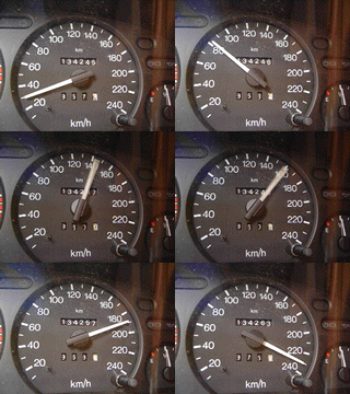
Vss supplys a square signal. 1.3889Hz/ Km/h or 5000 pulse by Km Let’s make a variable frequency generator in order to simulate the speed.
Components needed
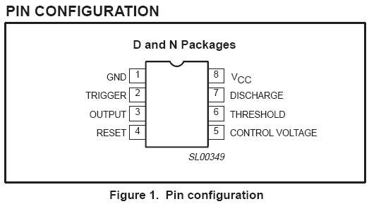
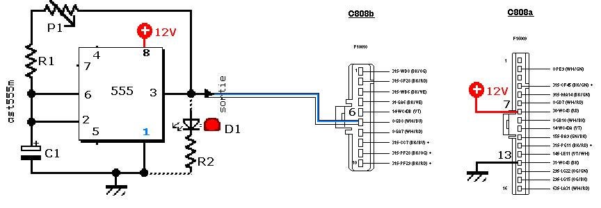
A power supply (12v) A NE555? A 10µF capacitor (C1) A resistor of 200 Ohms (R1) Another resistor of 560 Ohms (R2) with a LED 20mA (D1) (optional) And a variable resistor (range 0 – 10 KOhms?) (P1)
This is the schematic :
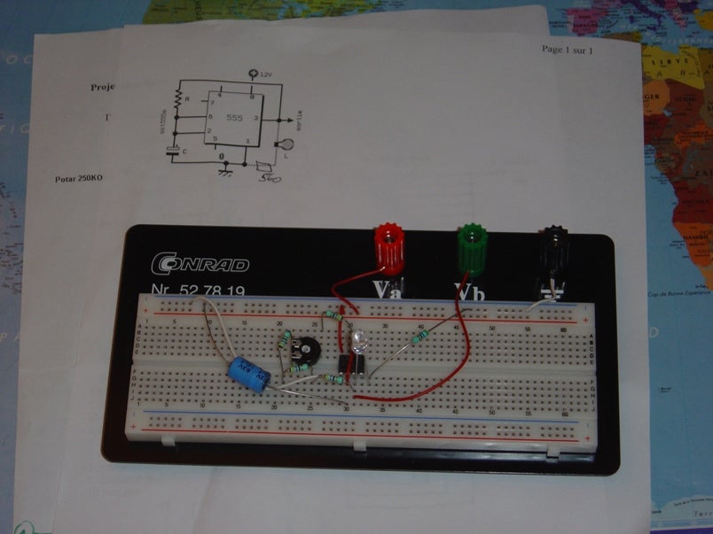
Built :
And connected :
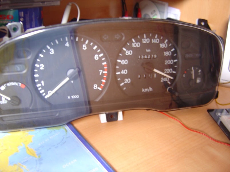
Now you can wait until you arrive to mileage you want. Enjoy!!! or play with it
Fitting
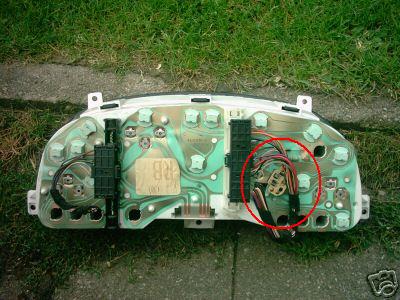
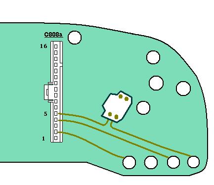
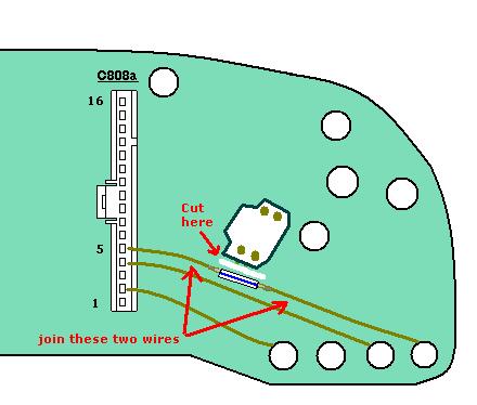
First thing, remove the airbag management off the new one, and adapt it to the old one to prevent the airbag warning light being constantly on. Look at the small card, and cut the wire which goes from the pin 5 and from the airbag warning light. Then join pin 5 to the warning light as it’s done on these pictures.
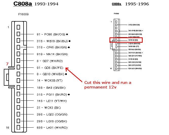
Then remove your old instrument cluster, look at your plugs, on the longest, run a permanent 12v (otherwise each time you will put 12v your needle of speed will jump) to the pin 7. I took the wire from the cigarette lighter but you can take it from another source like the radio
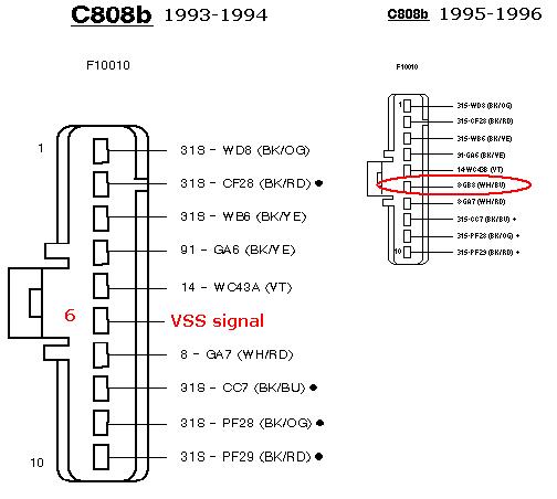
Last modification, now look at your shortest plug, run a new wire (VSS signal (vehicle speed sensor)) from your AWS unit or your trip computer (otherwise from your engine bay) to pin 6. Like it’s done on this picture.
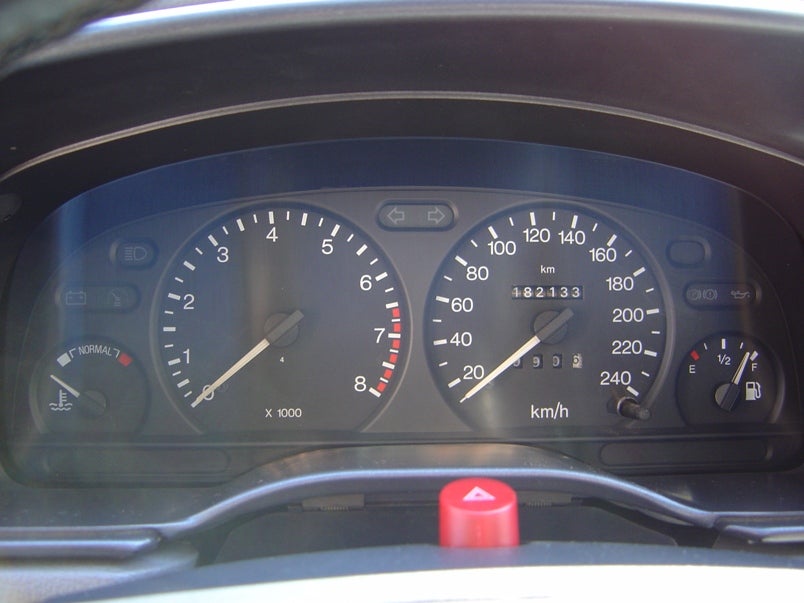
Finally plug in the speedo, check you haven’t blown any bulbs and enjoy!!!!!
That's it!
Extra Addition
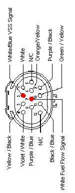
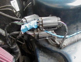
What if I have neither an AWS or Trip Computer You need to run a wire from the big plugs near the airbox. This wire needs to run from pin 2 shown below:
 Your Privacy Choices